Simple Air Compressor Setup Diagram for Beginners Guide
A simple air compressor setup diagram is a visual map that shows how every part of your compressor connects and works together. Whether you are a DIY enthusiast or a shop owner, understanding this diagram helps you install, troubleshoot, and maintain your system safely. This guide walks you through each component, wiring step, and safety tip so you can set up your compressor with confidence and avoid costly mistakes.
Setting up an air compressor for the first time can feel overwhelming. There are wires, hoses, valves, and gauges everywhere. But here is the good news. A simple air compressor setup diagram turns all that confusion into a clear picture. Once you understand what each symbol and line means, the whole process becomes much easier.
This guide is designed for beginners who want to set up their compressor correctly the first time. We will walk through every major component, explain how they connect, and share practical tips that save time and money. By the end, you will feel confident reading and even drawing your own setup diagram.
Key Takeaways
- Know Your Diagram: A setup diagram shows how the motor, pump, tank, pressure switch, and regulator connect.
- Safety First: Always disconnect power and release tank pressure before working on your compressor.
- Correct Wiring Matters: Proper electrical connections prevent damage and extend compressor life.
- Match Components Carefully: Using the right parts for your compressor model ensures peak performance.
- Maintenance Keeps It Running: Regular checks on hoses, filters, and connections prevent breakdowns.
- Start Simple: Beginners should follow a clear diagram step by step rather than improvising.
📑 Table of Contents
- What Is a Simple Air Compressor Setup Diagram?
- Essential Components of an Air Compressor Setup
- Step-by-Step Air Compressor Setup Process
- Reading and Understanding Compressor Wiring Diagrams
- Safety Tips for Your Compressor Setup
- Common Setup Problems and How to Fix Them
- Quick Tips for a Perfect Setup
- Expert Insights on Compressor Setup Diagrams
- Key Takeaways
What Is a Simple Air Compressor Setup Diagram?
A simple air compressor setup diagram is a drawing that shows how all the parts of a compressor system connect to each other. Think of it like a map. Instead of streets and buildings, it shows the motor, pump, tank, pressure switch, hoses, and regulator. Each part is drawn as a simple symbol, and lines connect them to show the flow of air and electricity.
These diagrams are essential for several reasons. First, they help you understand the air compressor installation process before you start. Second, they make troubleshooting much faster when something goes wrong. Third, they ensure that your compressor wiring follows safe electrical practices. Without a diagram, you are essentially guessing, and guessing with electricity and compressed air can be dangerous.
There are two main types of diagrams you will encounter. A pneumatic diagram shows the air flow path. A wiring diagram shows the electrical connections. Both are important, and most beginner guides cover both in a simplified format.
Why Beginners Need Diagrams
Compressors come in many sizes and styles. A small pancake compressor for a home garage looks very different from a large two-stage compressor in a professional shop. But the basic setup principles stay the same. A diagram gives you a universal language to understand how any compressor works. It removes the guesswork and helps you follow compressor setup instructions with confidence.
When you look at a diagram for the first time, you might feel lost. That is completely normal. The key is to learn what each symbol means. Once you recognize a few common icons, the rest starts to click. You will begin seeing how the pieces fit together like a puzzle.
Essential Components of an Air Compressor Setup
Before you read any diagram, you need to know the parts. Every air compressor setup diagram includes these core components. Let us break them down one by one.
The Motor
The motor is the engine of your compressor. It draws in electrical power and converts it into mechanical motion. This motion drives the pump that compresses air. In a simple air compressor setup diagram, the motor is usually shown as a circle with the letter “M” inside or a simple rectangle.
Motors come in different sizes measured in horsepower (HP). A typical home compressor has a 1 to 5 HP motor. The motor is connected to the electrical supply through a pressure switch that turns it on and off based on air demand.
The Pump
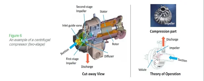
The pump is what actually compresses the air. It takes in atmospheric air and squeezes it into a smaller volume, which increases the pressure. In diagrams, the pump is often shown as a series of connected circles or a box with arrows indicating air movement.
The pump connects directly to the motor shaft. When the motor runs, the pump spins and creates compressed air. The type of pump (reciprocating, rotary screw, or scroll) affects how the diagram looks, but the basic connections remain similar.
The Air Tank
The tank stores compressed air so you have a ready supply when you need it. In a compressor setup schematic, the tank appears as a large cylinder shape, often with a drain valve at the bottom and a safety relief valve on top.
The tank connects to the pump outlet and to the output hose through a check valve. This valve prevents air from flowing back into the pump when the motor is off. It is a small but critical part of the system.
The Pressure Switch
The pressure switch is the brain of your compressor. It monitors the air pressure in the tank and tells the motor when to start and stop. When the pressure drops below a set level (the cut-in pressure), the switch tells the motor to turn on. When the pressure reaches the top level (the cut-out pressure), the switch shuts the motor off.
In a wiring diagram, the pressure switch appears as a square with electrical lines running to and from the motor. Understanding how the pressure switch wiring works is one of the most important parts of setting up a compressor.
The Regulator and Gauge
The regulator controls the output pressure that reaches your tools. Not all tools need the same pressure. A nail gun might need 90 PSI, while a paint sprayer might work best at 40 PSI. The regulator lets you dial in the right pressure for each tool.
The pressure gauge shows the current output pressure. In a setup diagram, these are shown as small circles with a needle indicator, connected to the output line after the regulator.
Hoses and Fittings
Hoses carry compressed air from the tank to your tools. They connect using quick-connect fittings that make it easy to switch between tools. In diagrams, hoses are shown as straight lines with connector symbols at each end.
Using the right hose diameter matters for performance. A 3/8-inch hose works well for most home tasks, while a 1/2-inch hose handles higher airflow demands. Always check that your fittings match the hose and tool connections.
Step-by-Step Air Compressor Setup Process
Now that you know the parts, let us walk through the actual setup process. Following a simple air compressor setup diagram step by step ensures that nothing gets missed.
Step 1: Choose the Right Location
Place your compressor on a flat, stable surface. Good ventilation is essential because compressors generate heat. Keep it away from flammable materials and moisture. If you are setting up outdoors, make sure the area is covered to protect the motor and electrical connections from rain.
Also consider noise levels. Compressors can be loud, so placing them near a wall or in a corner can amplify the sound. A well-ventilated garage or workshop corner works best for most home setups.
Step 2: Connect the Power Supply
Before connecting any wires, make sure you understand your compressor’s electrical requirements. Most home compressors run on a standard 120-volt outlet, but larger units need 240 volts. Check the nameplate on the motor for the correct voltage and amperage.
Use a dedicated circuit for your compressor. Do not plug it into an extension cord or share the circuit with other power tools. The compressor wiring should go directly from a wall outlet or a hardwired connection to the pressure switch, and then to the motor.
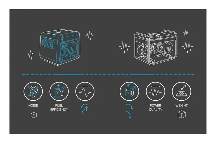
If your setup requires a generator, make sure it can handle the startup surge. For example, running a what size generator for 30 amp RV air conditioner requires similar power calculations. Always choose a generator rated for at least 1.5 times the compressor’s running amps to handle the motor startup.
Step 3: Attach the Pressure Switch
The pressure switch connects between the power supply and the motor. Follow the wiring diagram that comes with your compressor. Typically, you will connect the hot wire from the power source to the pressure switch input, and then run a wire from the switch output to the motor.
Set the cut-in and cut-out pressures according to your tank size and intended use. The pressure switch adjustment screws control these settings. Turn them carefully and check the readings with a gauge before running the compressor under load.
Step 4: Install the Check Valve and Tank Connections
The check valve sits between the pump outlet and the tank inlet. It allows air to flow into the tank but prevents it from flowing back. This is a critical safety component. Without it, compressed air would escape back through the pump when the motor stops.
Thread the check valve onto the pump outlet and the tank inlet. Use Teflon tape on all threaded connections to prevent air leaks. Tighten firmly but do not overtighten, which can crack the fitting.
Step 5: Connect the Regulator and Output Hose
Attach the regulator to the tank output port. The regulator should be installed between the tank and the output hose. This gives you control over the air pressure delivered to your tools.
Connect the output hose to the regulator using a quick-connect fitting. Make sure the hose is free of kinks and damage. Route the hose so it does not create a tripping hazard in your workspace.
Step 6: Test the Setup
Before using any tools, run a full test. Turn on the compressor and let it build pressure. Watch the pressure gauge to confirm the motor turns off at the correct cut-out pressure. Then use a tool and verify that the output pressure stays steady at your regulator setting.
Listen for any unusual sounds. A clicking pressure switch is normal. But grinding, squealing, or loud banging means you should shut off the compressor immediately and check for problems.
Reading and Understanding Compressor Wiring Diagrams
A compressor wiring diagram can look intimidating at first glance. But once you learn the basic symbols, reading them becomes second nature. Here are the most common elements you will see.
Common Wiring Symbols
- Circle with M: Represents the motor.
- Square with lines: Represents the pressure switch.
- Wavy lines: Represent the electrical power supply.
- Straight lines: Represent wires connecting components.
- Ground symbol: A horizontal line with three descending vertical lines, showing the safety ground connection.
Understanding the Circuit Path
In a typical setup, power flows from the wall outlet to the pressure switch. The pressure switch then sends power to the motor. When the tank pressure reaches the cut-out level, the switch breaks the circuit and the motor stops. When pressure drops to the cut-in level, the switch closes the circuit again and the motor starts.
This on-off cycle is controlled entirely by the pressure switch. Understanding this cycle helps you set the correct pressures and troubleshoot issues when the compressor does not start or stops too early.
Common Wiring Mistakes to Avoid
- Connecting the motor directly to power without a pressure switch.
- Using wire gauge that is too thin for the motor’s amperage.
- Skipping the ground connection for safety.
- Mixing up the hot, neutral, and ground wires.
- Not securing wire connections with proper terminals or connectors.
Each of these mistakes can lead to motor damage, electrical fires, or personal injury. Always double-check your wiring against the diagram before powering on the compressor for the first time.
Safety Tips for Your Compressor Setup
Compressed air is powerful, and electricity is dangerous. Following safety guidelines protects both you and your equipment.
Always Release Tank Pressure Before Maintenance
Before opening any tank valve or performing maintenance, open the drain valve to release all stored pressure. A tank full of compressed air can cause serious injury if opened unexpectedly. Make it a habit to check the gauge and confirm zero pressure before working on the tank.
Use the Correct Pressure Relief Valve
Every compressor tank should have a pressure relief valve. This valve automatically releases air if the pressure exceeds safe limits. Check that this valve is installed and functioning before you run the compressor for the first time. A blocked or missing relief valve can lead to a tank explosion.
Keep the Area Clean and Dry
Water and electricity do not mix. Keep your compressor setup area dry and free of debris. If you are using the compressor in a damp environment, use a ground fault circuit interrupter (GFCI) outlet to protect against electrical shock.
Wear Proper Protective Equipment
Safety glasses are a must when working with compressed air. Air particles can cause serious eye injuries. Wear hearing protection if your compressor is loud, and steel-toed boots if you are working in a shop environment.
Regular Inspection Checklist
- Check hoses for cracks or wear before each use.
- Inspect all fittings for air leaks.
- Verify the pressure gauge reads accurately.
- Drain moisture from the tank after each use.
- Check the oil level if your compressor is oil-lubricated.
- Test the pressure relief valve monthly.
Common Setup Problems and How to Fix Them
Even with a clear diagram, you might run into issues during setup. Here are the most common problems beginners face and how to solve them.
Compressor Will Not Start
If your compressor does not turn on, check the power supply first. Make sure the outlet is working and the circuit breaker has not tripped. Next, check the pressure switch. If the tank pressure is above the cut-in level, the switch will not close the circuit. Reset the switch by draining a small amount of air from the tank.
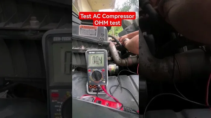
Also check the wiring connections. A loose wire at the pressure switch or motor terminal can prevent the compressor from starting. Use a multimeter to verify power is reaching the motor.
Compressor Runs but Does Not Build Pressure
This problem usually points to a leak or a faulty check valve. Inspect all fittings and hoses for air leaks. You can use soapy water on each connection to find leaks, which will show as bubbles. If the check valve is stuck open, air flows back into the pump instead of building pressure in the tank.
Pressure Switch Cycles Too Frequently
If the compressor turns on and off rapidly, the pressure switch settings may be too close together. Adjust the cut-in and cut-out pressures to create a wider range. Also check for air leaks in the hoses or fittings, which can cause the tank to lose pressure faster than normal.
Motor Hums but Does Not Start
A humming motor that does not start may have a faulty capacitor or a seized pump. The capacitor provides the extra boost the motor needs to start. If it is worn out, the motor will hum but not turn over. This is a repair best left to a qualified technician.
Air Leaks at Fittings
Air leaks waste energy and reduce compressor performance. The most common cause is loose or improperly sealed fittings. Turn off the compressor, release the pressure, and re-tighten each fitting. Apply Teflon tape to all threaded connections to create a proper seal.
Quick Tips for a Perfect Setup
- Print your simple air compressor setup diagram and keep it near the compressor for quick reference.
- Label all wires and fittings during installation so you can troubleshoot faster later.
- Take photos of your setup from multiple angles. These can be helpful if you ever need to call a technician.
- Keep spare fuses, pressure switches, and quick-connect fittings on hand.
- Read the owner’s manual for your specific compressor model before starting any setup work.
- Use a pressure regulator even for simple tasks. It gives you precise control and protects your tools.
Expert Insights on Compressor Setup Diagrams
Experienced technicians always emphasize the importance of understanding your specific compressor model. Not all compressors are wired the same way. A simple air compressor setup diagram for a small oilless compressor will look different from one for a larger two-stage oil-lubricated compressor.
One pro tip is to trace the air flow path with your finger on the diagram before you start any physical work. This mental walkthrough helps you understand the sequence of connections and catches potential issues before they become real problems. It also helps you understand the pneumatic system diagram logic, which applies to many other compressed air tools and systems.
Another valuable insight is to never skip the grounding step. A proper ground connection protects you from electrical shock and prevents static buildup that can damage sensitive compressor components. It is a small step that makes a big difference in safety.
When in doubt about any electrical connection, consult a licensed electrician. Compressor motors draw significant current, and incorrect wiring can trip breakers, damage the motor, or create a fire hazard. An electrician can also help you size your electrical circuit correctly for your compressor’s amperage requirements.
Key Takeaways
- A setup diagram is your roadmap: It shows every connection from power supply to output hose.
- Learn the core components: Motor, pump, tank, pressure switch, regulator, and hoses form the foundation.
- Follow the steps in order: Location, power, pressure switch, check valve, regulator, then testing.
- Safety is non-negotiable: Always release pressure, use relief valves, and wear protective gear.
- Troubleshoot systematically: Start with the simplest explanation and work your way to complex issues.
- Maintain regularly: A well-maintained compressor setup lasts for years of reliable service.